


Related products

AXS-120 - Last-mile/Access compact OTDR
Compact yet mighty, the AXS-120 brings EXFO’s renowned OTDR accuracy, reliability and durability to the field in a compact form factor.

AXS-130 - compact OTDR
Optimized for FTTx/MDU fiber deployments and troubleshooting, suitable for metro. Live and/or dark fiber testing capability in a compact yet mighty form factor.
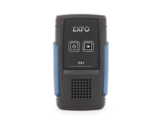
EX1 - FTTH and Business Services tester
The smallest Gigabit, GPON and WiFi testing solution available
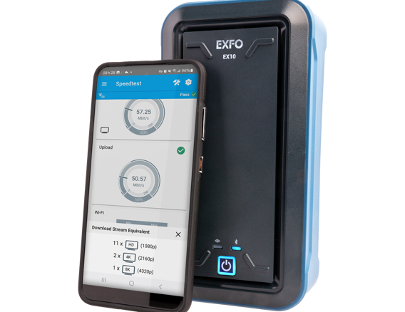
EX10 - Multigigabit residential & business services tester
Validate bandwidth speeds up to full line rate 10 Gigabit Ethernet, test residential Wi-Fi 7 and monitor residential quality of experience
EXFO Exchange - sharing test results and ensuring compliance
Paired with EXFO’s leading test instruments, this trusted cloud-hosted solution drives an entire ecosystem, while integrating seamlessly with existing operation processes.
FIP-200 - Connector Checker™
Purpose-built for broadband service activation. Compact and intuitive, the FIP-200 Connector Checker™ provides visually clear pass/fail results adapted to broadband in the field.
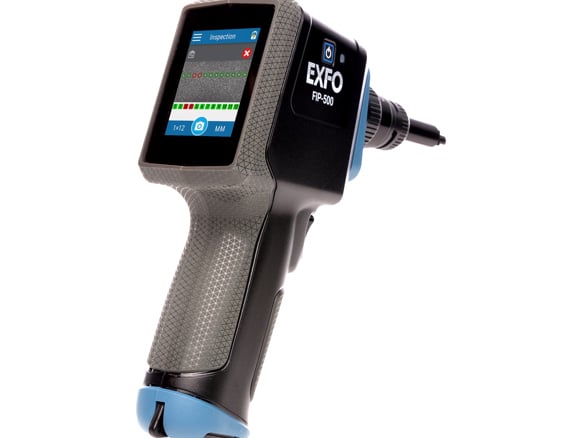
FIP-500 - Fiber inspection scope
Industry’s first AI-driven endface analysis for simplex, duplex and multi-fiber connectors. Delivers reliable and repeatable results with a self-contained, fully automated tool for zero-button testing all day—no need to recharge batteries or offload results.
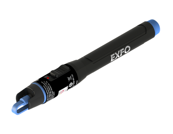
FLS-190 - High-power visual fault locator (VFL)
This high-power pocket-sized VFL is an essential tool for any technician testing fiber over long distances.

FTB Lite 720D - connected access OTDR
Optimized for the construction and troubleshooting of singlemode and multimode access networks.

FTB Lite 730D - connected PON/metro OTDR
Optimized for FTTx/MDU fiber rollouts and troubleshooting. Can also test metro networks.
FTBx-88260 - 10M to 100G network tester
Customizable 10M -100G testing, including 100ZR coherent support, with multi-interface flexibility via EXFO’s Open Transceiver System (OTS)
FTBx-88480 Series - dual-port 1G-400G, 800G-ready testers
Compact, multiservice dual-port testing (1G-400G, 400ZR and 400ZR+). Includes EXFO’s modular Open Transceiver System (OTS). Software upgradeable to 800G.
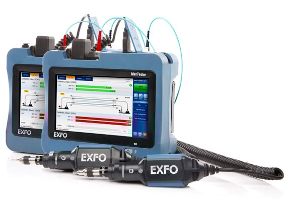
MaxTester 945 - Fiber certifier OLTS
Optimized for Tier-1 fiber certification (data center, enterprise) and designed to help installation contractors, network engineers and IT maintenance technicians achieve faster, first-time-right-system acceptance.
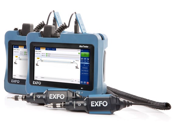
MaxTester 945 - Telco OLTS
First tablet-inspired, multifunction optical loss test set (OLTS) delivering insertion loss, optical return loss and fiber length measurements at two wavelengths in five seconds via fully automated bidirectional FasTesT™ analysis.
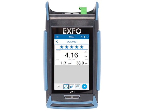
OX1 - Optical Explorer - Industry's first optical fiber multimeter
Fiber optic tester that performs link verification and automated fault tracking in seconds. Empowering frontline technicians to explore further and do more.
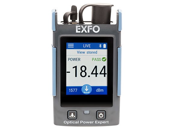
Optical Power Expert (PX1) - Connected optical power meter
Power meter with Bluetooth connectivity, a wide touchscreen and best-in-class optical performances.
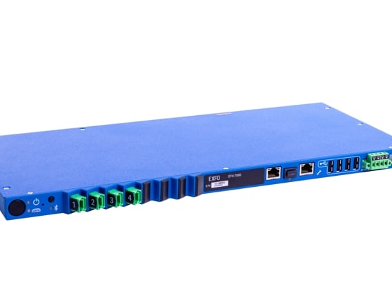
OTH-7000 - Optical test head
Compact OTDR-based remote test unit designed for fiber network monitoring and troubleshooting
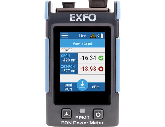
PPM1 - Service activation PON power meter
Versatile dual-layer tester purpose-built for PON service activation, with added broadband capabilities.

EXFO RFTM - Remote Fiber Testing and Monitoring
Intelligent OTDR-based solution for testing and monitoring fiber links (P2P and PON) from buildout to maintenance.