Characterizing Advanced Modulation Formats Using an Optical Sampling Approach
With bandwidth demand growing and fiber availability going down, carriers and equipment manufacturers have no choice but to turn to high-speed optical transmission systems to increase network capacity. However, traditional one-bit-per-symbol modulation schemes, such as OOK or DPSK, do not offer the spectral efficiency necessary to significantly increase the overall data-carrying capacity of optical fibers. Moreover, if scaled up to much higher transmission speeds, these traditional modulation formats become very sensitive to chromatic dispersion (CD) and polarization-mode dispersion (PMD), rendering them unusable on existing networks. The influential Optical Internetworking Forum (OIF) has recommended using fully coherent four-bit-per-symbol DP-QPSK (dual-polarization quadrature phase-shift keying) modulation format for 100 Gbit/s system design, since it is both spectrally efficient and highly resilient to CD and PMD (when coupled with suitable signal processing algorithms). In addition, the industry is already seriously looking at longer-term evolution with modulation schemes such as 16-QAM and OFDM.
These radical changes in modulation formats bring huge challenges to equipment manufacturers and eventually carriers, as these modulation schemes cannot be characterized using traditional test instruments and methods that are sensitive only to the time-varying intensity of the signal light, and not to the phase of the light signal. Therefore, in addition to well-known eye diagram analysis, which provides intensity and time information for OOK signals, new measurements must be performed to retrieve the phase information, and constellation diagram analysis is the base of it.
Different instruments can be used to recover the intensity and phase information critical to fully and properly characterize advanced modulation schemes like QPSK, 16-QAM or their dual-polarization versions: high-resolution optical spectrum analyzers (OSAs), modulation analyzers based on real-time electrical sampling oscilloscopes, as well as modulation analyzers based on optical sampling. Each approach has its advantages and disadvantages; therefore, when characterizing high-speed transmitters, it is important to understand the key elements affecting the constellation diagram recovery and the quality of the measurements that can be obtained from it.
Measurement Approaches
One approach to recover intensity and phase information of a signal is to employ a high-resolution optical spectrum analyzer. Such sophisticated instruments use non-linear effects combined with a local oscillator to recover both amplitude and phase information from the signal. The intensity and phase vs. frequency information is then converted to time domain using a fast Fourier transform (FFT). However, this results in severe limitations, including the incapacity to capture long sequences of data or recover the information from framed OTU-4 data.
The second (and probably most obvious) approach is to use a real-time electrical sampling oscilloscope—i.e., sampling light with electronics—to acquire data samples in a similar way as any coherent receiver would do it, by sampling at the symbol rate. This approach yields very accurate information on the symbol position on the constellation and can provide bit-error-rate information on samples of the data stream. However, their limited effective bandwidth and the impedance mismatches typically found when interfacing with high-speed electronics make it impossible to obtain accurate transition information and perform distortion-free waveform recovery.
Finally, an alternative approach is to employ a modulation analyzer based on optical sampling—i.e., characterizing light with light. This approach uses short laser pulses as a stroboscope to effectively open a sampling gate in order to generate samples with energy proportional to the power of the input signal. These samples are then detected by lower-speed electronics. The main advantages of this stroboscopic optical sampling approach are its very large effective bandwidth (arising from its high temporal resolution) and the absence of impedance mismatch, allowing distortion-free waveform recovery at signal-under-test symbol rates in excess of 60 Gbaud. Optical sampling oscilloscopes and modulation analyzers typically have an effective bandwidth 5 to 10 times larger than electrical sampling solutions.
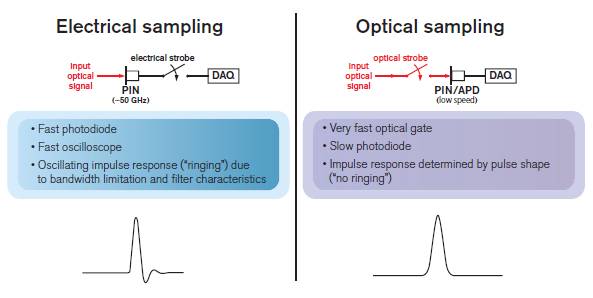
Figure 1. Electrical vs. optical sampling techniques
An electrically sampled waveform is affected by the instrument, whereas an optically sampled waveform gives the true shape.
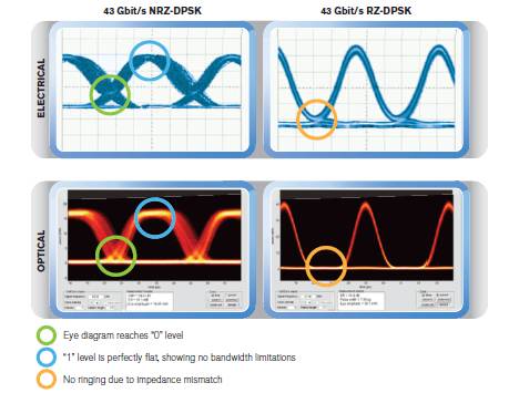
Figure 2. Waveform recovery comparison between electrical and optical sampling
Measurements that Match the Objectives
When designing transmitters or transmission systems, the objective is always the same: transmit as much data as possible, as fast as possible, in the smallest channel bandwidth possible, and making sure it can be received error-free at the other end. Several parameters will affect the performance of transmitters and systems, which is why performing the right optimization and verification is critical.
Until now, for transmission based on more conventional modulation formats like NRZ (non-return to zero) or DPSK (differential phase-shift keying), sampling scopes providing eye diagram analysis have been used to characterize and optimize transmitters. Measurements like eye opening, signal-to-noise ratio (SNR), skew, extinction ratio, rise/fall time and jitter are obtained using such instruments.
Advanced modulation formats with coherent transmission require similar analysis, yet since the information is not only included in the intensity of the signal but also in its phase, a constellation analyzer is the instrument required to test transmitters and systems. This requires new measurements, such as I-Q imbalance and error vector magnitude (EVM), which refers to the deviation of the measured constellation when compared to the ideal constellation, phase or intensity error, to gather key information on the tuning of the modulator or pulse carver, for example. If dual-polarization transmission is used, variations between the two polarizations also need to be identified and measured since they may indicate problems in the transmitter design or balance.
At the system level, one of the parameters generally used to qualify performance—and considered the ultimate indicator that the data sent through the network is received without errors—is the bit error rate (BER). When transmission is good and BER is low, there is no need for additional troubleshooting. A high BER value, however, triggers key questions: What if the BER increases to a point where the system cannot completely correct errors? What information can be gleaned from the BER apart from revealing that the system is not working?
This is when it is critical to rely on a test instrument able to provide distortion-free waveform recovery and precise transition information to allow engineers to identify the causes of the transmission problems, such as crosstalk between polarizations, dispersion, signal-to-noise ratio, etc.
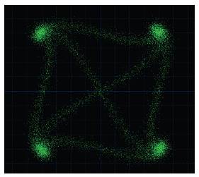
Figure 3. Constellation diagram showing minor chromatic dispersion impact
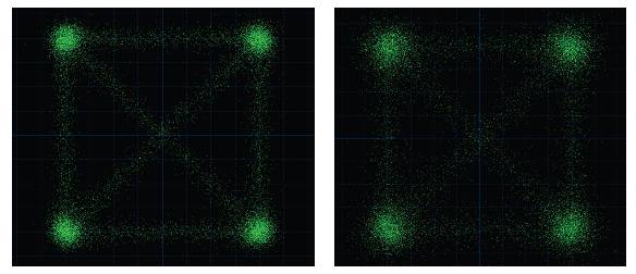
Figure 4. Impact of poor SNR on constellation diagram
Bit-Error-Rate Measurement Using a Modulation Analyzer
As mentioned above, BER is an important test to carry out on any transmission system. When performing this test using a modulation analyzer, whether based on electrical real-time sampling or optical sampling, a very important limitation must be taken into consideration.
Over sufficiently long periods (i.e., more than a few seconds), only a small percentage of the symbols are actually sampled, either in a short duty cycle “burst mode”, as is generally the case with electrical real-time sampling, or in an undersampling manner, as with “equivalent-time” optical sampling. In practice, data transfer and processing take most of the time during each sampling cycle, i.e., between 95% and 99% of the cycle, depending on the sampling method and the processing power of the test instrument.
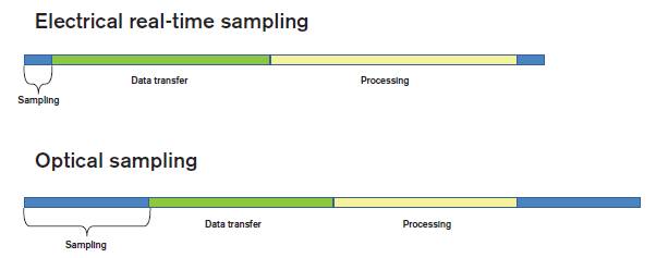
Figure 5. Sampling duty cycle for electrical real-time and optical equivalent-time sampling.
The consequence of this short duty cycle is simple. The BER estimated using a modulation analyzer will be valid only if errors have a normal statistical distribution. None of the sampling approaches will allow measurement of glitches that might generate errors. In order to “capture” such short error bursts, a true real-time sampling device (such as a receiver) is required.
The other relevant question with regards to a BER value obtained with a modulation analyzer pertains to the hardware. Since the modulation analyzer generally employs a different receiver front-end than the actual receiver used in the customer system, we need to determine if the BER measured with it is representative of the true BER that can be achieved with the receiver—a question whose answer relies on both the quality of the instrument and the quality of the receiver.
From this perspective, the BER estimated using a modulation analyzer can only be used as a general indication of the transmission quality and certainly not as an absolute confirmation that the system is optimized and will provide the best possible performance.
Advantages of Optical Equivalent-Time Sampling
Modulation analyzers based on optical sampling, like EXFO’s PSO-200, offer many key features for the characterization and optimization of 40/100 Gbit/s (and beyond) Ethernet transmitters and systems:
- High temporal resolution in the range of a few picoseconds
- Extremely low intrinsic timing jitter and phase noise
- No impedance mismatch created by high-speed electronic components, as the sampling is performed at the optical level and only low-speed electronics are required
- Enough effective bandwidth to allow characterization of signals up to 100 Gbaud
Not only can such instruments provide similar information and measurements as real-time electrical sampling solutions, but they also achieve very precise and accurate constellation diagrams, including transition information and distortion-free waveform recovery for today’s and tomorrow’s modulation formats and transmission speeds. In essence, the waveform captured this way is the true optical waveform unimpaired by the testing instrument. Optical modulation analyzers can therefore be viewed as the “golden testing instrument” that can serve as a baseline and common standard in the industry.


