Mastering the Mueller method with swept IL-PDL measurements

Passive optical components: what to test and why?
Passive optical components are at the heart of today’s network infrastructure. They are used to filter and route wavelength division multiplexing (WDM) signals in the core, metro and access networks. Optical components such as wavelength selective switches (WSS), multiplexers (DWDM, CWDM), optical add-drop multiplexers (OADM) and PON filters play a critical role and must meet tight optical specifications. This is why they need be tested quickly and reliably. In parallel, the development of new technologies such as 5G and photonic integrated circuits (PIC) is driving new types of passive components such as ring resonators with an ever-increasing complexity.
Assessing the optical characteristics of passive optical components in R&D and manufacturing is vital and starts by measuring two key optical parameters: insertion loss (IL) and polarization dependent loss (PDL). IL represents the optical loss of the device under test, whereas PDL quantifies the variation of the loss when the polarization of the light incident on the component varies.
For WDM components with a strongly wavelength dependent profile, IL and PDL must be measured as a function of wavelength with high resolution to accurately derive analysis parameters used for pass/fail analysis in acceptance test reports, such as:
- Central wavelength
- Offset versus grid wavelength
- IL at central wavelength and at grid wavelength
- PDL at central wavelength and at grid wavelength
- Bandwidth
- Pass-band ripple
- Isolation (adjacent and non-adjacent)
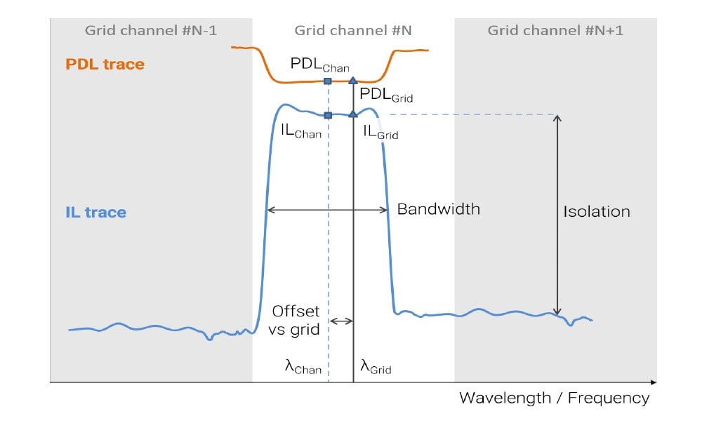
Figure 1. Schematic representation of common analysis parameters used for WDM filter analysis.
4-state IL-PDL measurement with the Mueller method
The 4-state Mueller method has become an industry standard for swept IL-PDL measurement of WDM components. This method relies on measuring the insertion loss of the DUT consecutively with 4 distinct states of polarization generated using a polarization state generator or a polarization controller. The Mueller method is well-established thanks to its high accuracy and to the possibility to achieve picometer resolution over wide measurement ranges while maintaining fast measurement times. The Mueller method also scales very well and is equally suited to measure components with just a few and 100+ outputs.
EXFO’s CTP10 and CT440 are two component testers that operate with the T100S-HP tunable laser as a complete swept solution for IL-PDL measurement using the Mueller method.
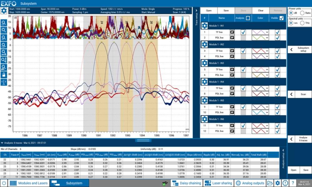
Figure 2. Swept IL-PDL measurement of a 6 channels 100 GHz DWDM mux/demux performed with the CTP10 test platform. Measurement parameters: 1530 – 1620 nm wavelength range, 1 pm sampling resolution, 100 nm/s laser sweep speed. The total measurement time was 12.5 seconds.
Navigating the murky waters of swept PDL measurements
The Mueller method is not always well-understood and suffers from common misconceptions despite being the most common measurement method for IL-PDL testing. This sometimes results in shortcomings in the measurement configuration or in the way IL and PDL are calculated, affecting the accuracy of the IL and PDL results. The difficulty to experimentally verify PDL results against a certified reference measurement makes it very challenging to pinpoint such shortcomings, leaving questionable results sometimes undetected for years.
Three tips for accurate and reliable PDL testing:
- Accounting for the wavelength dependence of the state of polarization.
When using an external polarization controller, it can be tempting to set the desired state of polarization at the start of the sweep and assume that the output polarization remains constant across the wavelength range of the laser sweep. This is not the case in practice, and polarization state generators or polarization controllers always exhibit a wavelength dependence that must be accounted for best PDL accuracy. - Having a system approach rather than a box approach.
It is paramount to think about the measurement system as a whole and evaluate the performance of a test solution as such. The specifications of each instrument taken on its own matter but may not always truly reflect how the complete swept solution will perform. One could for example ask about the noise floor of the detectors, but a more relevant question when evaluating the performance of the whole system would be about the IL dynamic range.
Assessing the specifications of custom test solutions that use instruments from multiple vendors lies in the hands of the end user and is very challenging, if not impossible. This often translates into questionable performance. On the other hand, complete IL-PDL test solutions are more likely to natively integrate all the features and best practices to perform accurate measurements right out of the box. - Validating PDL accuracy.
PDL accuracy is the main quality indicator of a PDL measurement, yet this point is all too often overlooked. WDM optical components typically have PDL values as low as just a few tenths of a dB, putting even more emphasis on the need for highly accurate test solutions. The difficulty to assess or verify experimentally the PDL uncertainty of a measurement system also highlights the need to have clear and explicit specifications for reliable measurements without assumptions.
Would you like to delve into greater details about the formalism of the Mueller method for swept IL-PDL measurements? Read our free white paper which also highlights the underlying raw data and best practices for understanding the Mueller method and achieving reliable and accurate PDL measurements. It’s a must-read for every test engineer involved in swept IL-PDL measurements.