Overcoming Connection Reflectance and Network Failure in the 10G/40G/100G/400G Data Center Migration

The inevitable obsolescence of copper infrastructures and the migration to optical fiber 10G to higher gigabit Ethernet environments brings exciting opportunities, challenges, and complexities to data center network managers and contractors. One such network complexity that is often neglected is connection reflectance that can lead to serious downtime and network failure that can also compromise the success of the migration. By using suitable testing equipment and changing current testing practices to more future-oriented methods to accommodate the surge of new changes in connectivity, such as parallel optics, PAM4, Encircled Flux MMF requirements, and OM5 wide band multimode fiber (WBMMF) with short wavelength division multiplexing (SWDM), what could be a serious network problem can be easily and quickly solved.
Connection Reflectance at the Patch Panel—The Permanent Link is Changing
As transmission speeds increase, especially for 40, 100, and 400G on the horizon, fiber insertion loss and connection reflectance requirements must become more stringent. For example, migrating from 10GbE to 25GbE provides 2.5x the throughput per lane, while choosing the 25G line rate for a 100G (4x25) link may require a new transceiver. It is, therefore, debatable that reflectance specifications published by some major industry standard bodies of -20dB (ISO/IEC 11801 2010; TIA-568.3D 2013) for multimode fiber and -35dB UPC (TIA-568.3-D 2013, ballot 6) for singlemode fiber are inadequate. -35dB for multimode and -40 to -45dB reflectance for singlemode may be a more realistic customer requirement for an existing patch panel equipped with LC/UPC (for use with QSFP28 4x25G,100G). Reflectance thresholds should also consider that the permanent link is changing for the high-density and scalable data center network with increased adoption in optimizing parallel optics using only multifiber MPO connectors that via patch cords are directly connected into the transmitter. This approach is ideal for the 40-100G and future 400G migration and uses ribbon fiber for fast and easy installations, saving both time and labor dollars.
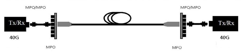
Image 1: MPO-MPO (40G-100G-400G) IEEE 802.3ba
MPO connectors for both multimode and singlemode, however, may require tighter loss tolerances. Unlike SC and LC single-fiber connectors, MPO connectors can be more susceptible to developing poor physical contact after multiple connects and disconnects that can lead to degraded connector insertion loss and reflectance. For multimode, Elite grade (for US Conec’s MTP brand) or Ultra UPC and for Singlemode, APC (angled physical contact) polishes help to minimize reflectance issues.
Modifying Testing Procedures for Reflectance and Changes in the Data Center
Data center fiber infrastructure advancements have evolved rapidly in the past few years and the fiber infrastructure and transceiver roadmap is becoming clear. Therefore, network operators and contractors are now in a position to plan their own roadmap for bandwidth growth. Through studies and R&D, EXFO engineers have become cognizant of macrotrends that are dictating network infrastructure deployments and bandwidth migration for years to come and have designed and launched testing equipment to reflect those trends and technology advancements. One such trend is that many hyperscale and other large data centers are adopting singlemode fiber only, while negotiating good price points for the cost of the more expensive singlemode transceivers. Leveraging new modulation formats, such as PSM4 & PAM4, and parallel optics into their infrastructures, large data centers are deploying 100G (4x25G) today while planning not so distant future 200G and 400G deployments.
Since not all data centers are created equal, a second trend observed is that for smaller footprint enterprise data centers, multimode is still a good option, even if maximum fiber distances to meet the requirements of 100G/200G/400G over MMF would be constrained at maximum 60-70 meters to allow a safe migration to 200G/400G. The recent ratification by TIA’s TR-42 Engineering Committee of OM5 fiber allows WDM (4 wavelengths) in the 850nm region and serves as yet another example that multimode fiber is a credible future-proofing medium. A successful plan to meet new technology requirements, however, like it or not, requires new testing practices and procedures.
A common testing practice in today’s data centers is to first use an advanced OLTS (optical loss test sets) to assess the important end-to-end loss budget of the fiber optic interconnect infrastructure and length of the fiber links to ensure that signals are successfully transmitted by the transceiver per the specific application. An Encircled Flux compliant OLTS, such as the MAX-945 iCERT QUAD, can provide bidirectional testing in 2 wavelengths in less than 3 seconds! How and when an OLTS is used for testing, however, must be modified to consider factors including substantial shrinkage of the loss budget (1.5dB over MMF for 40G/100G), for example, and making the precise assessment of where the insertion loss is distributed along the fiber link or what portion goes to cassettes and connections versus the fiber itself. The reduction in loss budget and headroom becomes an even more complex issue when testing 10G deployments with 25G and/or future 50G lane deployments for 100G/200G/400G, as well as the fact that higher speed networks require additional testing including reflectance of the connections at the patch panel. To bypass testing these systems, as some companies do, can lead to disastrous network failures that could have been easily avoided.
One of the primary sources of fiber link loss and multimode reflectance is fiber mismatch that creates connector offsets when using a VSCEL that underfills the core with light and underestimates losses or an LED that overfills and yields overestimated losses when testing. Studies indicate that there can be up to a 60% variance in power measurement due to VCSEL’s susceptibility to under-fill the fiber core, leading to inaccurate and random measurements. To achieve repeatability, consistency, reproducibility, and validity of testing results, Encircled Flux metrics and methods should be employed as images 2-4 illustrate.
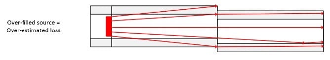
Image 2: VCSEL
Image 3: LED
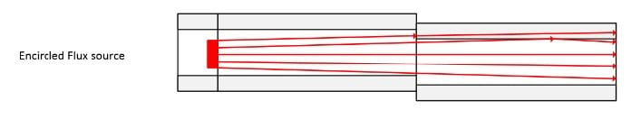
Image 4: Encircled Flux
Poor physical connectivity can result in high bit error rates, potential packet loss and latency, which is why an Encircled Flux compliant light source, such as the MAX-945 iCERT QUAD, is advised.
Whenever OLTS results suggest a fault, there is a greater than 95% chance that the problem lies with the connectors. The OLTS, however, cannot evaluate or measure insertion loss or reflectance and it cannot detect the source of the problem or the location of the faulty connector(s). That’s the job of an Encircled Flux compliant OTDR, such as the FTB-720C QUAD iOLM, that measures localized insertion loss and reflectance for each connector on the fiber link and precisely detects the position of the fault(s) for all input and output connectors to minimize network downtime. It also provides information about total ORL, link loss, and the length of the fiber link.
Since reflectance is such a serious issue, a logical recommendation is to test first with the OTDR to ensure that all connectors are working efficiently ensuring first-time-right migration to high speed links. Then, follow with OLTS testing to meet industry standard related compliance requirements and ensure optimum end-to-end physical infrastructure transmission performance.
One of the most prevalent causes that effects return loss is contamination of the connector by transference of the oil from the technician’s hand or fingertips during installation and testing as shown in Image 5. Oil contamination results in major changes to return loss (10dB to 12dB at 10G) in this singlemode fiber example. The oil does not create an air gap at10g so it does not impact insertion loss, but at 25G the return loss could be great enough to cause serious network failure due to significant degradation of bit-error-rate test BERT) performance.
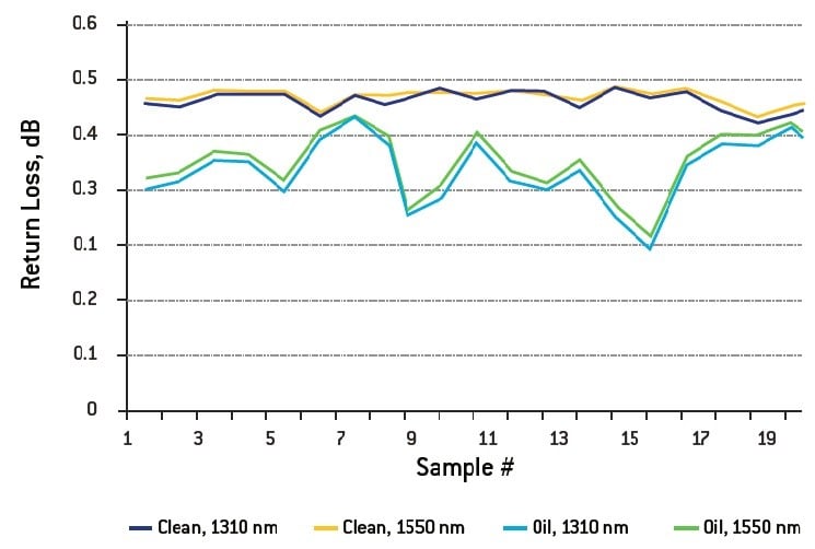
Image 5: Return Loss of Clean versus Oil Contaminated Connector (10dB – 12dB average difference in Return Loss)
Since there is zero tolerance for any dirt, dust, or debris on connectors, fiber inspection and cleaning using an FIP-435B Optical Scope is a must each time a connector is manipulated and prior to any reconnection of connectors and OLTS or OTDR testing to keep your network up and running 24-7-365.
The Future is Now
With the rapid growth of bandwidth requirements and the migration beyond 10G, the future is here and now. Old 10G connectivity and testing procedures and habits are no longer sufficient or economically justifiable. Continuing to run the data center network with older SFPs, for example, is no longer viable as it would require too much fiber and active 10G ports. Moreover, the fact that a link was running smoothly at 10G is not a guarantee that 100G/200G/or 400G will run fine on the same existing architecture; it’s a risk to assume that it would. It’s not a guarantee either that new network build installations using the best quality components will not run into flaws, faults, losses, and reflectance.
The best assurance for a successful migration and a low maintenance zero-downtime network is to test effectively and frequently as recommended, ultimately saving your organization significant time, labor costs and worries, since your network will be running at peak performance.
For over 30 years as the market leader in fiber-optic test and measurement and having pioneered fiber equipment into the data center, OFS understands the needs and technologies of our customers— so much so that EXFO’s broad OLTS, OTDR, and other product lines covering the entire spectrum of fiber testing and service assurance are already equipped with next generation advancements— providing you with the most advanced testing equipment and QoS/QoE for today, tomorrow, and years to come. For more information about the latest testing solutions, view Nicholas Gagnon’s on-demand CI&M webinar presentation.


