Service Activation Made Easy
The service-activation phase may seem very straightforward at first glance, but, in fact, the task should not be taken lightly, as this is the moment when the customer experience begins. The service-activation scheme can be very different, depending on the fiber-to-the-home (FTTH) network topology. New trends such as deployments in multidwelling or multitenant units (MDU/MTUs) often include pre-engineered plug-and-play components with multiple connection points or, alternately, they can also be deployed using an all-spliced approach. Another thing to keep in mind is that FTTH networks link one location to multiple locations, also called point-to-multipoint networks, where each drop fiber corresponds to a specific customer or optical network terminal (ONT), as opposed to legacy networks, where a fiber typically links one location to another.
In terms of data storage, passive optical network (PON) service activation therefore brings about two new dimensions:
- Results should be linked to customers or ONTs instead of fibers
- More than one test location may be required, typically two or three
Since the service-activation phase is often performed by subcontractors, the reporting and data authenticity protection have become major factors in PON deployments, where hundreds of results may be generated for a single PON activation. So, following the right steps in the day-to-day activations ensures a smooth workflow and high productivity.
Unique Workflow Management Solution
The PPM-350C PON Power Meter comes with a full-fledged software solution, helping users from front to back office. The unit also includes a Job Editor mode, as well as post-processing and reporting tools.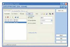
Figure 1. The PPM-350C's Data Transfer tab
In Job Editor mode, managers and technicians alike can pre-configure upcoming jobs by entering information about a specific customer or an ONT name/number, along with location, ONT and optical line terminal (OLT) identification corresponding to the network topology.

Figure 2. The PPM-350C's Job Editor mode
Once these jobs are created using a straightforward PC software application, they can be loaded onto the unit through a USB connection. Thanks to this innovative tool, users can now:
- Integrate their workload directly into their PON power meter
- Avoid bringing a pile of network plans and workload material in the field
- Start testing right away without worrying about file names
- Easily keep track of service-activation results per customer or ONT installation
- Save time
The PPM-350C’s unique data management structure not only allows users to save results of pre-configured jobs, but also save results per OLT or central office (CO), per ONT and even per location.
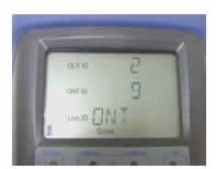
Figure 3. The PPM-350C's PON-adapted graphical user interface-storage screen
Multiple Testing Locations
Verifying optical levels at various locations along the same fiber path helps users pinpoint problems and/or defective components before activating a customer’s service. Since FTTH network problems are often caused by dirty or damaged connectors, component inspection greatly reduces troubleshooting, as power levels are verified for each network section. It is also highly recommended to inspect each connection point using a fiber inspection probe, such as the FIP-400, before each power measurement.
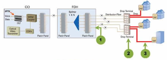
Figure 4. PPM measurements at different locations
Testing Points
- By performing a power-level certification at the splitter—more specifically at the output— users can verify if the splitter branch is working properly. This simple assessment allows them to confirm that all network components from the CO (including the feeder fiber, or F1) to the splitter output are in good condition. Typically, the FDH includes SC/APC or LC/APC connectors.
- By performing a power-level certification at the drop terminal, users can characterize the distribution fiber and the drop terminal ports. Usually, a splice tray is included within the drop terminal, which can cause macrobend problems. Typically, the drop terminal includes OptiTap™ weatherproof connectors or mechanical splices.
- The fiber connecting the drop terminal to the customer premises, also called the last mile or drop cable, is generally installed during service activation. To ensure reliable services to the customer, the network and the customer ONT must meet their specifications.
- Truly rugged and weatherproof
- All-wavelength testing
- Pass-through connection for burst measurements
- PON-adapted storage interface
- Pass/fail automated assessment
- Job Editor mode
- Reporting software
- Proprietary data format ensuring authenticity of test result
The best way to guarantee this is to perform a pass-through connection to fully characterize all operating wavelengths (upstream and downstream) in the PON. The only way to achieve this at the service-activation phase is to use a dual-port PON power meter with a pass-through connection, like the PPM‑350C; otherwise, it will only certify downstream signals from the CO.
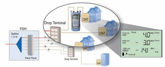
Figure 5. Pass-through testing of all wavelengths
Using EXFO’s FastReporter for True FTTx PON Reporting
Back at the office, users can download all test results stored in the unit directly into FastReporter. Post-processing functions such as pass/fail assessment with specific thresholds can be performed.
Having named all files prior to the testing session, users will not waste time renaming them. Since the naming structure was done correctly from the start, reporting is performed in a few minutes.
FastReporter offers an innovative FTTx Service Activation reporting tool, which generates reports with the following information:
1. Power level for each wavelength and each location
2. Time stamp for each measurement
3. Pass/warning/fail status
4. Thresholds used to perform the pass/warning/fail assessment
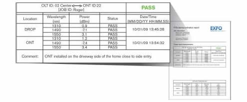
Figure 6. Screenshot of FTTx service activation reporting tool
The Right Tools
EXFO’s line of PON-optimized products addresses each phase of FTTx network deployments. For service-activation tasks, the PPM-350C PON Power Meter teamed with an FIP-400 Fiber Inspection Probe and an AXS-100 Handheld OTDR enable quick and easy service activation. The PPM-350C was designed with true PON service-activation realities in mind. With its innovative workflow management, this instrument demystifies and simplifies service-activation tasks by offering easy-to-use features:
Click here for more details about the PPM-350C.


