Carrier Ethernet Basics

This article is part of EXFO’s Carrier Ethernet Basic’s Educational Series—a comprehensive guide to network and service performance testing—which is comprised of six informative modules, specifically designed to assist you with Carrier Ethernet service testing.
As technologically sophisticated businesses and residential consumers continue to drive the demand for premium, high-bandwidth data services such as voice and video, service providers worldwide must evolve their transport infrastructures to support these bandwidth and quality-intensive services. No longer is an all-IP core sufficient—providers must now expand their IP convergence to the edge/metro network, in a cost-effective, quality-assured manner.
What is Carrier Ethernet?
Ethernet has long been accepted as an inexpensive, scalable data-networking solution in LAN environments; however, the stringent quality of service (QoS) expectations of today’s service offering require that service providers find solutions to tap into the cost-effectiveness of Ethernet without sacrificing the benefits of connection-oriented (albeit it costly) time-domain multiplexing (TDM) solutions such as SONET/SDH.
Comprehensive Ethernet testing immediately at service turn-up is now essential in order to ensure service quality and increase customer satisfaction. Customer service level agreement (SLAs) dictate certain performance criteria that must be met, with the majority documenting network availability and mean-time-to-repair (MTTR) values, which are easily verified. However, Ethernet performance criteria are more difficult to prove, and demonstrating performance availability, transmission delay, link burstability and service integrity cannot be done precisely with only a single ping command. Carrier Ethernet, therefore, is the extension of Ethernet that enables service providers to provide premium Ethernet services.
Transport Media
The diagram below outlines the different media used within a Carrier Ethernet network and indicates where they are commonly deployed:
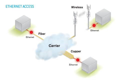
Copper
To this day, copper cabling (i.e., insulated twisted copper wires) is still one of the most widely used media in Carrier Ethernet due to its existing vast deployment and its relatively low cost. It is almost everywhere as it was the media of choice to deliver plain old telephony service (POTS) to homes and businesses. Leveraging this infrastructure, service providers can avoid building out new and costly networks, as they address markets with lower-rate traffic of up to 1 Gigabit per second (Gbit/s) and begin to carry higher-speed traffic (in some cases up to 10 Gbit/s). Ethernet’s inherent scalability gives carriers a highly flexible platform for delivering incremental services to smaller enterprises, branch offices, cellular towers and other sites. However, copper is subject to both electromagnetic interference and cross-talk, which can negatively affect the reliable transfer of digital data—and at high speeds, the problem is even worse.
Microwave
Ethernet is also used for mobile backhaul, the distance from a cell tower to a switching office or between switching offices. The medium used is actually microwave-over-the-air. Microwave radio is a popular infrastructure choice for wireless operators. Ethernet-enabled microwave is becoming an increasingly important component of a wireless infrastructure. The increasing interest in microwave is driven by the higher bandwidth demands at the base station sites and the requirement to provide a substantial reduction in operational costs of backhauling the data traffic. The growth of the wireless industry combined with the proliferation of the mobile backhaul will only contribute to increase the use of microwave radio as a transport medium.
Fiber
Since fiber can carry much more information than copper, carrier Ethernet service providers typically use fiber to transport high-speed traffic (usually 1 Gbit/s or more) over long distances or within the network core. Fiber is used with SONET/SDH, dense wavelength-division multiplexing (DWDM) or optical transport networks (OTNs). Fiber cabling may have an initial higher cost, but even at the fastest speeds, it is entirely resistant to both cross-talk and electromagnetic interference, therefore it can provide much more reliable data transmission. As the demand for bandwidth and speed increases, the need to implement fiber on networks, even at the business site, is growing. However, the main issue with fiber is the high cost of deployment and maintenance.
Carrier Ethernet Network Services
The two basic Ethernet service types defined by the Metro Ethernet Forum (MEF) are:
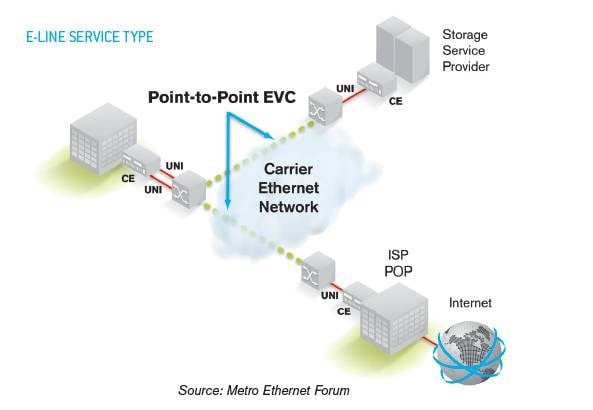
Ethernet Line (e-Line)
Delivering point-to-point connectivity, E-Line services are used to create Ethernet private line services, Ethernet-based Internet access services and point-to-point (P2P) Ethernet VPNs.
E-Line Variants
- Ethernet Private Lines
This service consists of a P2P connection that uses dedicated bandwidth, either virtually concatenated SONET/SDH channels or reserved packet bandwidth in a packet-switched network. The customer’s Ethernet frames stay strictly separated from others’ at the Ethernet layer, and the customer will always have the contracted bandwidth rate available (also known as the committed information rate (CIR)). In this regard, the Ethernet private line is much like legacy TDM-based private lines, yet offers the benefit of a native Ethernet interface to the customer and to the network operator’s edge equipment. Like typical TDM private lines, the Ethernet private line can be deployed to support a number of different carrier services such as Ethernet Internet, network services access or LAN-to-LAN interconnect—in which the customer owns one or both ends of the connection. The Ethernet private line is the simplest E-Line service to deploy. Service providers typically provide these services from a multiservice provisioning platform (MSPP), which acts as the demarcation between the customer’s network and the carrier’s SONET/SDH transport network.
- Ethernet Virtual Private Line
For the Ethernet virtual private line, the rules are slightly different. In this service, the customer still gets point-to-point connectivity, but over shared bandwidth instead of dedicated. The shared bandwidth can be a TDM channel in the transport network or the switched-fabric bandwidth of switches and routers in the packet network. The service can either be offered as best-effort or with SLAs specifying CIR and other critical network parameters, such as latency. This service is quite similar to frame relay and its model of creating networks using permanent virtual circuits (PVCs). MEF defines Ethernet virtual private line service as a P2P Ethernet virtual connection (EVC) between two subscribers. Multiple EVCs can be combined to provide hub-and-spoke architectures in which multiple remote offices all require access to a head office, or multiple customers all require access to managed services from an operator’s point of presence (POP).
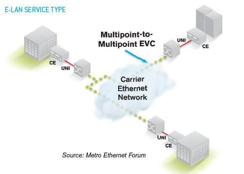
Ethernet LAN (e-LAN)
Delivering multipoint-to-multipoint (any-to-any) connectivity, E-LAN services are designed for multipoint Ethernet VPNs and native Ethernet transparent LAN services.
E-LAN Variants
- Ethernet Private LAN
An Ethernet private LAN (EPLAN) service provides multipoint connectivity over dedicated bandwidth, i.e., it can connect two or more subscribers. Subscriber data sent from one customer site can be received at one or more of the other customer sites. Each site is connected to a multipoint-to-multipoint Ethernet virtual circuit (EVC) and uses dedicated resources so that the different customers’ Ethernet frames are not multiplexed together. As new sites are added, they are connected to the same multipoint EVC, thus simplifying provisioning and service activation. From a subscriber standpoint, an EPLAN makes multiple LAN sites look like a single, yet immense, LAN.
- Ethernet Virtual Private LAN
The Ethernet virtual private LAN (EVPLAN) has gone by many names over the past two years, from virtual private LAN service (VPLS) to transparent LAN service (TLS) to virtual private switched network (VPSN). Regardless of how it is termed, the EVPLAN is a network service providing layer 2 multipoint connectivity between Ethernet-edge devices. Customer separation is accomplished via encapsulation using VLAN tags or other encapsulation technologies such as MPLS. The EVPLAN is a cost-effective service for the service provider, as it can leverage shared transmission bandwidth in the network. However, because it is a multipoint service, it can be complex to administer. The operator must implement protection, bandwidth profiles, congestion management, buffering, etc.—these are much more complex to implement in EVPLANs when compared to P2P services.
Carrier Ethernet Applications
Carrier Ethernet services are mainly used in two segments:
Business Services
The deployment of carrier Ethernet services within businesses will continue to grow with the demand of higher and higher bandwidth; this is driven by the requirements of enterprises—not only for data services, but also for voice and video services over their network.
Site-to-site access, data centers, server consolidations, disaster recovery, service orientated architecture, internet access, software-as-a-service (SaaS) and converged networking are just a few applications that require high bandwidth and low latency.
One of the major benefits of Ethernet for business services is cost reduction. Global availability of standardized services reduces the cost of implementation. The familiarity of IT departments with Ethernet makes the implementation of Carrier Ethernet services easier and cheaper. In essence, Carrier Ethernet brings the benefits of the Ethernet cost model to metro and wide-area networks. New applications requiring high bandwidth and low latency—which was previously not possible or prohibited due to high costs—can now be implemented.
Another major benefit of Carrier Ethernet is performance. That is, in part because inherently, Ethernet networks require less processing to operate and manage. They also operate at higher bandwidths than other technologies. It is also the most suited solution for voice, video and data because of its low latency and delay variation. Carrier Ethernet services also provide a high level of flexibility, which is ideal for applications such as site-to-site access that by the nature can have unpredictable and varying bandwidth requirements.
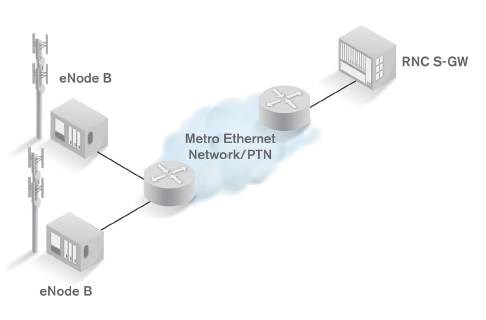
Mobile Backhaul Services
As the backhaul network infrastructure evolves to support packet-based transmission, mobile operators face numerous challenges, resulting from the shift from managing network performance to managing service performance. Testing the network with a simple ping is no longer an option. In addition to assessing the network’s performance, operators now must constantly validate and measure key performance indicators on a per-service basis.
Today, and in the years to come, backhaul networks will be made of a mixture of both E1/T1 (for voice) and Ethernet/IP (for data services) technologies. This hybrid-network approach offers an economical solution for potential traffic bottlenecks with the increased traffi c of non-real-time data.
As carrier Ethernet networks mature, wireless backhaul will eventually become totally packet-based; this will simplify network architecture, reduce costs and provide the necessary scalability for expected growth with data-centric applications.
Key Performance Indicators
Key performance indicators (KPIs) are specific traffic characteristics that indicate the minimum performance of a specific traffic profile. The following KPIs directly influence the performance of backhaul networks.
- Frame delay, or latency, is the difference in time from the moment a frame or packet leaves the origination port and the moment it arrives at the destination port. It has a direct impact on the quality of real-time data, such as voice or video. Management services such as synchronization protocols, which communicate between the BSC and mobile devices, must have a very fast response time. This helps to ensure quality voice transmission, cell handoffs, signaling and reliable connectivity.
- Frame loss is a serious problem for all real-time services such as voice or live video, as well as for synchronization and management of traffic control. Lost packets cause poor perception quality, and lost control packets increase latency and may cause connectivity failures—and even dropped calls.
- Bandwidth refers to the maximum amount of data that can be forwarded. This measurement is a ratio of the total amount of traffic forwarded during a measurement window of one second. Bandwidth can either be ‘committed’ or ‘excess’ with different performance guarantees.
- Frame delay variation, or packet jitter, refers to the variability in arrival time between packet deliveries. As packets travel through a network, they are often queued and sent in bursts to the next hop. Random prioritization may occur, resulting in packet transmission at random rates. Packets are therefore received at irregular intervals. This jitter translates into stress on the receiving buffers of the end nodes, where buffers can be overused or underused when there are large swings of jitter. Real-time applications are especially sensitive to packet jitter. Buffers are designed to store a certain quantity of video or voice packets, which are then processed at regular intervals to provide a smooth and error-free transmission to the end user. Too much jitter will affect the quality of experience (QoE)—where packets arriving at a fast rate will cause buffers to overfill, leading to packet loss; while packets arriving at a slow rate will cause buffers to empty, leading to still images or sound.
Key Technologies Overview
MPLS
IP/multi-protocol label switching (MPLS), an IEEE standard, is an established transport method that transparently switches data (packets or frames) from multiple protocols (ATM, frame relay, Ethernet, etc.) across an all-IP backbone. With full class-of-service (CoS) and virtual LAN (VLAN) support, MPLS is an ideal solution for carriers wanting to extend the life of legacy TDM-based services in the core. Modifications are being made to the standard to increase traffic engineering capabilities (MPLS-TP), which will enable IP/MPLS to support the advanced quality of service needed to extend the solution out to the metro edge.
MPLS-TP
With the movement toward packet-based services, transport networks have to encompass the provision of packet-aware capabilities while enabling carriers to leverage their installed transport infrastructure investments. MPLS transport profile (MPSL-TP) is a derivative of MPLS designed for transport networks. It supports the capabilities and functionalities needed for packet-transport network services and operations through combining the packet experience of MPLS with the operational experience and practices of existing transport networks. MPLS-TP enables the deployment of packet-based transport networks that efficiently scales to support packet services in a simple and cost-effective way.
PBB-TE
Provider backbone bridge traffic engineering or PBB-TE (also referred to as PBT) is an alternative Ethernet-based implementation that enables carrier-grade provisioning and management of connection-oriented transport services across an all-IP MAN and core network by disabling the flooding/broadcasting and spanning tree protocol features. It is an evolution of MAC-in-MAC by making it connection-oriented. PBB-TE separates the Ethernet service layer from the network layer; its flexibility also allows service providers to deliver native Ethernet initially and MPLS-based services—i.e., virtual private wire service (VPWS) or virtual private LAN service (VPLS)—if and when they are required.
PTN
The packet transport network (PTN) is the next generation of networks designed around the best elements of traditional TDM technologies and the emergent packet technologies. It is typically deployed at two layers. At the access layer, PTN provides convergence of multiple services by converging TDM and packets into the PTN cloud. TDM packets are encapsulated and forwarded as packets in the PTN cloud while native Ethernet/IP packets are encapsulated and forwarded in the same PTN cloud.
PTN networks overcome many of the challenges of carriers by providing the efficient data transport of packetized technologies with the fault detection and resiliency of TDM-based networks. Service providers can now leverage the inherent advantages of Ethernet and TDM technologies, such as cost effectiveness, flexibility, multiservice applications as well as quality of service.
PWE3
Pseudo wire emulation edge-to-edge (PWE3) is a mechanism that emulates the essential attributes of a service such as ATM, frame relay or Ethernet over a packet switched network (PSN). PWE3 only provides the minimum required functionality to emulate the wire. From the customer perspective, it is perceived as an unshared link or circuit of the chosen service. PW3 specifies the encapsulation, transport, control, management, interworking and security of services emulated over PSNs.
To maximize the return on their assets and minimize their operational costs, many service providers are looking to consolidate the delivery of multiple service offerings and traffic types onto a single IP-optimized network. PWE3 is a possible solution since it emulates Ethernet frame formats over IP networks.
Circuit Emulation Services
Circuit emulation services (CES) is a technology used to carry T1/E1 services over asynchronous networks such as ATM, Ethernet. This paper focuses specifically on circuit emulation over Ethernet (CESoS). Service providers can now manage and provision time division multiplexing (TDM) leased lines via CESoS and endpoints terminating in the public switched telephone network (PSTN) or between enterprise endpoints. With this technology, service providers can now use TDM applications to leverage the advantages inherent in Ethernet such as: flexibility, cost-effectiveness and simplicity.
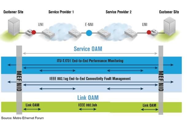
Ethernet OAM
Ethernet OAM draws on and includes existing standards such as IEEE 802.1ag for connectivity fault management (CFM), ITU-T Y.1731 for performance monitoring, 802.3ah or EFM (Ethernet in the first mile) for link monitoring, fault signaling and remote loopback for the access network.
OAM standards are used to troubleshoot networks, monitor performance, verify configuration and manage security. OAM functionality allows network operators to measure QoS attributes, such as availability, frame delay, frame delay variation (jitter) and frame loss. Ethernet OAM can also provide remote loopback, a feature often used to troubleshoot networks where all inbound traffic is immediately reflected back on the link.
At the device level, OAM protocols generate messages that are used by operations staff to help identify problems in the network. In the event of a fault, the information generated by OAM helps the operator troubleshoot the network to locate the fault, identify which services have been impacted and take the appropriate action. Also, just as it is important to keep the customers’ services running, operators must be able to prove that is the case, this is usually measured against an SLA, and the operator must have the performance measurements to manage customer SLAs. Finally, administration features include collecting the accounting data for the purpose of billing and network usage data for capacity-planning exercises.
Effective end-to-end service control also enables carriers to avoid expensive truck rolls to locate and contain faults, thereby facilitating reduction of maintenance costs. Intrinsic OAM functionality is therefore essential in any carrier-class technology and is a ‘must have’ capability in intelligent Ethernet network termination units.
Synchronization
As the network moves toward Ethernet as the transport technology of choice, synchronization remains a major issue. As Ethernet and TDM technologies continue to coexist, technologies like circuit-emulation services (CES) provide capabilities to map TDM traffic on Ethernet infrastructure and vice versa, enabling a smooth changeover for network operators transitioning to an all-packet network.
To interconnect these two technologies, frequency synchronization is key, since the TDM technologies have frequency-offset tolerances that are much more restrictive than the asynchronous Ethernet technologies. Ethernet relies on inexpensive holdover oscillators and can stop transmitting traffic or buffer data, while TDM technologies rely on the continuous transmission and presence of synchronization reference. Synchronous Ethernet solves these issues by ensuring frequency synchronization at the physical level.
However, since SyncE is a synchronization technology based on layer 1, it requires that all ports on the synchronized path be enabled for SyncE. Any node that is non SyncE-enabled on the path will automatically break the synchronization from this node. This is an issue for network providers that have a multitude of Ethernet ports between the primary synchronization unit and the edge device that needs synchronization as all the ports must be SyncE-enabled to synchronize to the edge. Such requirements can increase the cost of deployments as hardware and software upgrades can dramatically increase the total cost of ownership. SyncE also only focuses on frequency synchronization and does not guarantee phase synchronization—although the phase requirements can be somewhat assessed via SyncE.
Many services need synchronization, but wireless base stations today have the largest stake in frequency and time distribution. The frequency stability of the air interface between the cell tower and the handset supports handing off a call between adjacent base stations without interruption. Synchronization for base stations is therefore central to the QoS that an operator provides.
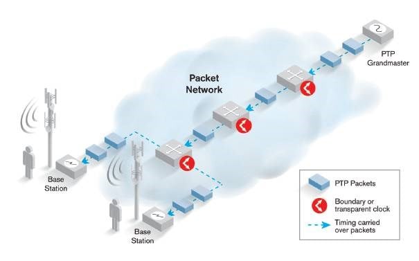
The next packet synchronization technology, the Precise Time Protocol (PTP) also referred to as the “IEEE 1588v2”, is specifically designed to provide high clock accuracy through a packet network via a continuous exchange of packets with appropriate timestamps. In this protocol, a highly precise clock source, referred to as the “grand-master clock” generates timestamp announcements and responds to timestamp requests from boundary clocks, thus ensuring that the boundary clocks and the slave clocks are precisely aligned to the grand-master clocks. By relying on the handover capability and the precision of the integrated clocks in combination with the continuous exchange of timestamps between PTP-enabled devices, frequency and phase accuracy can be maintained at a sub-microsecond range, thus ensuring synchronization within the network. In addition to frequency and phase synchronization, ToD synchronization can also ensure that all PTP-enabled devices are synchronized with the proper time, based on coordinated universal time (UTC).
The great advantages of PTP is that as a packed-based technology, only boundary and slave clock needs to be aware of the nature of the packets and therefore synchronization packets are forwarded as any other data packets within the network. This flexibility reduces the cost of ownership as the main upgrade to the networks are limited to synchronization equipment contrarily to the SyncE approach that requires both synchronization equipment and upgrade of all Ethernet ports on the link to SyncE specifications.