Overcoming Network Failures in C-RAN for 5G-Readiness

5G is the next evolutionary step in cellular communication positioned to become the global wireless standard for a totally connected society. In addition to bolstering gigabit speeds over mobile networks, 5G promises to support the massive growth of devices and connections, virtualization (NFV), 8k HD video streaming, exponential growth in traffic (global mobile data traffic grew 74% in 2015, alone), connectivity of the Internet of Things (IoT), and yet unidentified emerging technologies that meet the growing high bandwidth consumer demands for high-speed mobile broadband.
These demands are so monumental that 5G promises 1,000 x the mobile data and 10 to 100 x the number of connected devices of 4G, while delivering 1-10Gbit throughputs per user, 90% reduction in network energy usage, and just 1millisecond or less of end-to-end round-trip latency.
While users around the world are currently enjoying 4G/LTE and LTE-Advanced (LTE-A) mobile broadband services, standardization efforts for 5G have begun and many operators are planning for initial 5G trials. In fact, CNET is reporting that Verizon expects “some level of commercial deployment” of 5G to begin by 2017, much earlier than the 2020 5G standard adoption date. Since time is of the essence, mobile network operators (MNOs) should begin to roadmap and build major parts of their new Centralized-Radio Access Network (C-RAN) and cloud-RAN architectures.
Proper testing in the design-build is crucial for C-RAN and 5G deployment success. By using advanced equipment that in one test instrument integrates OTDR fiber testing at the physical layer with RRH and BBU emulation modes, CPRI protocol analysis and optical RF verification at the transport layer, and Ethernet link validation for testing the backhaul, MNOs are ensured to overcome inherent complexities and impairments of C-RAN/ cloud-RAN for a cost effective, low latency, and reliable “do-it-right-the-first-time” 5G-ready network.
The Building Blocks from FTTA to C-RAN to Cloud-RAN
Nowadays, the mobile industry has replaced much of its copper radio frequency (RF) cables with optical fiber for Fiber to the Antenna or FTTA, as Image 1 illustrates. The move from copper to fiber provides MNOs
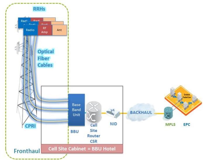
Image 1: Typical FTTA Architecture for 4G/LTE Cellular Deployments
with less noise, lower power requirements, and much higher bandwidth. Another important difference between FTTA and legacy copper cell towers is that with FTTA the remote radio unit, which was located at the bottom of the legacy cell tower, has now been moved to the tower top alongside the antennas and, in more recent cases, completely incorporated into the cell tower’s multiple antennas. The connection between the RRHs (remote radio head) and BBUs (base station units or base stations) is referred to as the fronthaul and uses the CPRI or OBSAI transport protocol. BBUs perform signal-processing functions and create the radio signal, whereas the RRHs convert the radio signal into an RF or wireless signal.
As Image 2 shows, one can make an analogy that building a 5G network is like building a house, with FTTA as the foundation for C-RAN and Cloud RAN, and Mobile Edge Computing being the last floor in order to complete the 5G network. Any deficiency or issue in the lower floors has a detrimental impact on the upper floors, as well as on the 5G network.
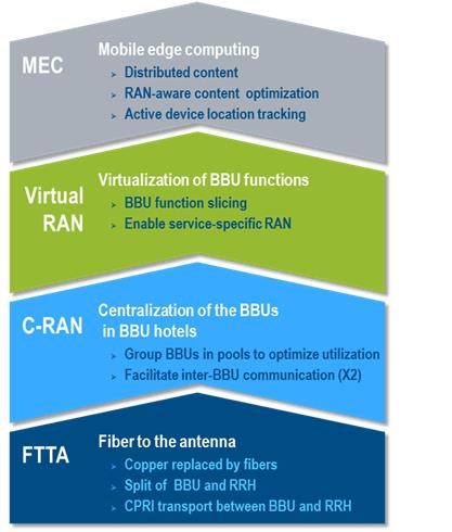
Image 2: The Building Blocks to Cloud RAN
Validation of FTTA at the rollout stage following physical-layer installation testing ensures the readiness of the antenna sites to support the next phase of centralized RAN and virtualization, and eventually 5G. The key physical layer testing at the FTTA fronthaul includes fiber connector inspection at each connection point with an inspection probe, such as the FTB-700G V2 Series’ FIP-400B Series probe that performs fast and easy pass/fail connector endface analysis, important for the detection of unclean connectors or connector endface damage that constitute more than 80% of network failures. The next phase of physical layer testing includes the installation of the fiber loop (Rx to Tx) at the RRH for loopback testing. This step is followed by the characterization of the end-to-end fiber link and the validation of loss budget with an OTDR, or its more advanced counterpart, EXFO’s iOLM. The patented iOLM intelligent Optical Link Mapper feature of the FTB-700G V2 testing unit turns traditional OTDR testing into clear, automated, first-time-right results for technicians of any skill level and eliminates the need to configure parameters or analyze multiple complex OTDR traces. The testing unit’s iLOOP feature, based on the loopback test method, is used to test 2 fibers at once directly on-site from the ground or base station.
Following the crucial physical layer testing, it is now necessary to conduct service validation with the FTB-700G V2’s CPRI protocol analyzer that eliminates unnecessary tower climbs by testing the health of the RRH from the bottom of the tower via BBU emulation. Other testing steps include BBU validation using RRH emulation followed by verification that small form factor pluggable (SFP) transceivers are installed and connected correctly for optimum transmission performance.
Now that the FTTA has been tested and validated for peak performance and QoS, MNOs can proceed with confidence to the next building steps for the 5G Cloud RAN network architecture. If the execution of the FTTA testing and validation is performed without quality or skipped altogether as some may do, the cell site will likely require retesting and costly troubleshooting.
A Closer Look at C-RAN, 5G, and Its Benefits
As with any new network architecture, there are significant benefits, opportunities and challenges; so is the case with Centralized RAN (C-RAN). Simply, the most concise definition of C-RAN is when the BBUs from the bottom of the tower are moved to a centralized location often called “BBU hotel,” typically in a central office or data center (see image 3). Notice that the mobile core is connected to the base station through an IP network constituting the backhaul. The centralization of the RAN is an enabling step for the transition to 5G, since 5G will be based on network slicing, end-to-end virtualization of the network, new radios with larger bands and new spectrum requirements, and the coordination of radio resources in a cloud-RAN.
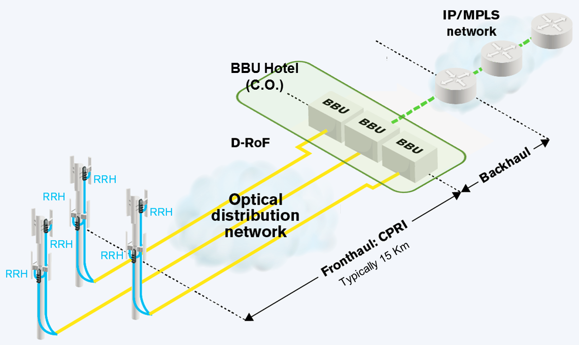
Image 3: Centralized RAN (C-RAN) Architecture
The eventual achievement of cloud-RAN is, therefore, dependent on successful BBU centralization. Cloud-RAN, to be more concise, is defined as the virtualization of all or part of the functions of the BBU.
C-RAN provides MNOs with multiple benefits including many that reduce Capex and Opex:
- Antenna site simplification
- Energy consumption gain (>50%)
- Improved efficiency of field services
- Reduction of footprint at cell site
- Less maintenance time and costs
- Monitoring and troubleshooting from a centralized location
- Faster and easier upgrade cycles
- Pool of BBUs in a secured place ensuring optimum traffic transmission, free from tampering and weather-related damage
To achieve cloud-RAN and the benefits it provides, it is important to understand the impairments inherent in C-RAN so that they may be overcome by effective testing using the FTB-700G V2 Series testing unit and the FTB-5700 for dispersion issues.
Overcoming the Challenges of C-RAN…The Road to 5G
One of the major challenges of the C-RAN infrastructure deployment involves the long distances between the centralized BBUs and the fronthaul FTTA area, as depicted in Image 4. This is why paying close attention to the quality of the FTTA deployment discussed earlier is so imperative. Longer distances of up to 15 miles in C-RAN imply attenuation, making the power loss budget more difficult to meet. Additionally, C-RAN introduces elements, such as WDM Multiplexers (MUXs) and Demultiplexers (DEMUXs), which significantly attenuate signals. At these long distances, close attention to macro-bends creating loss is vitally important, as well.
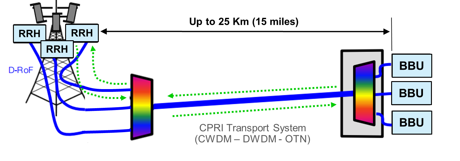
Image 4: C-RAN Distance Illustration
To calculate the power loss budget, it is important to always input the worst case scenarios conveyed on SFP specification sheets that provide minimum and maximum launch power information, such that Loss budget = SFP minimum launch power minus SFP sensitivity. Loss budgets vary widely between vendors and models. The following passive C-RAN example in Image 5 explains how total power loss can be calculated. In passive C-RAN, MUX/DEMUX loss must be considered. In active C-RAN, a separate loss budget should be computed between elements that feature optical to electrical and back to optical (O-E-O) conversion. Note that active C-RAN may be adequate for the power budget; but not for latency because of the regeneration of the transmission signal which introduces an important time delay.
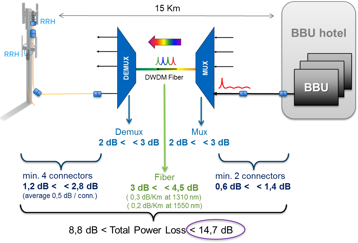
Image 5: Total Power Loss Example
Addressing the potential wavelength problems that may be encountered due to C-RAN’s long distances from the BBUs, we need to understand that in fronthaul backbone rings, wavelengths must be dropped to the correct tower by properly configuring each OADM and by connecting the fiber to the correct port. Different wavelengths emanate from the BBU hotel as depicted in Image 6. Common problems include connections that are not properly connected in the OADM, so that the blue wavelength, for example, which was intended for Tower A, is dropped to Tower B, making the network totally ineffective and susceptible to significant downtime.
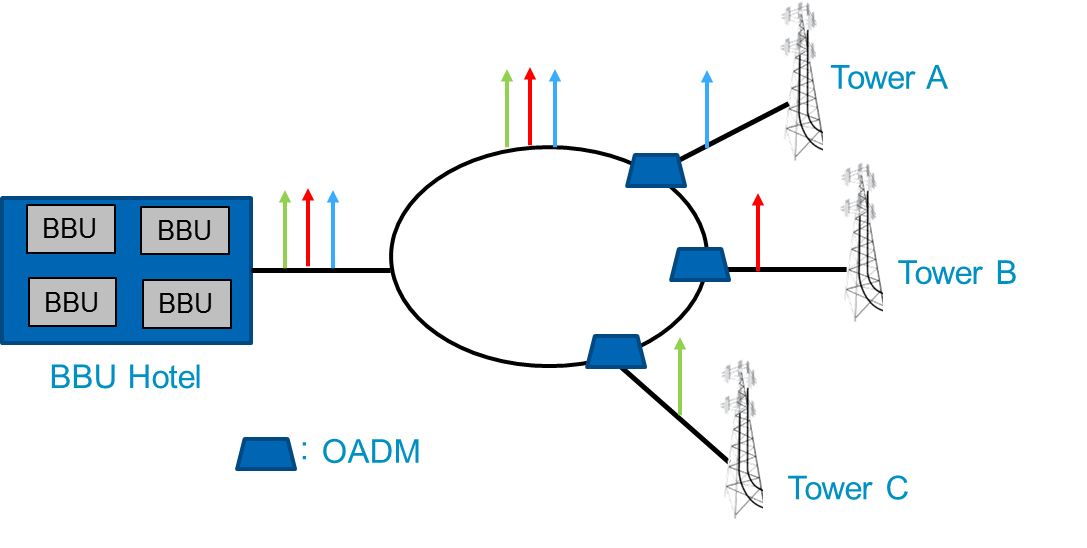
Image 6: Wavelength Length Issues due to Distance from BBU to RRH
To avoid this potential pitfall, CWDM or DWDM OTDRs operating at a specific CWDM or DWDM wavelength can be used to measure loss at signal wavelength, which is impossible to do with standard OTDRs. By knowing BBU-to-RRH distances, the OTDR can confirm that the wavelength is properly addressed.
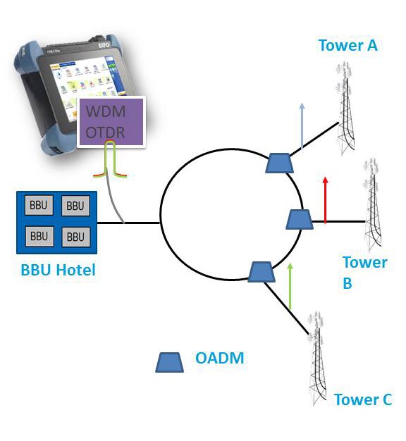
Image 7: Wavelength Length Issues Resolved
Since bandwidth-hungry mobile network demands are still growing at an unrelenting pace, including ultra-high resolution 4k TV streaming, the road to 5G and cloud-RAN will require data rates of 100G in the backhaul and, perhaps, in the fronthaul, as well. The increases in distance and faster data rates of C-RAN networks trigger occurrence of dispersion issues, so that MNOs should conduct thorough dispersion testing that is imperative for the 5G C-RAN migration.
There are 2 types of dispersion, Chromatic Dispersion (CD), which is pulse broadening due to different wavelengths inside a pulse of light raveling at different speeds, and Polarization mode dispersion (PMD), which is pulse broadening caused by the differences in propagation velocities for different polarization states. Both can lead to serious bit error rates (BER) that can potentially lead to network failure in extreme cases, as shown in Image 8.
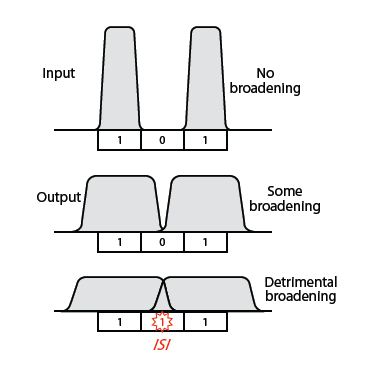
Image 8: Pulse Broadening Due to Dispersion
Dispersion issues may affect both the backhaul and fronthaul areas of the C-RAN network. The ITU G.650.3 standard states that dispersion should be tested when bandwidth reaches >10 GB/s. Due to the very nature of the dispersion phenomena, dispersion issues are more likely to occur as span lengths increase. It is usually recommended to test dispersion in spans longer than 10 km. Crucial dispersion testing is fast and easy with the FTB-5700, which is unique among available dispersion testers in that it is single-ended with both CD/PMD capabilities. The single-ended feature reduces by half or more the required technicians and associated costs, while ensuring strong infrastructures for both the fronthaul and backhaul 5G C-RAN network.
Conclusion
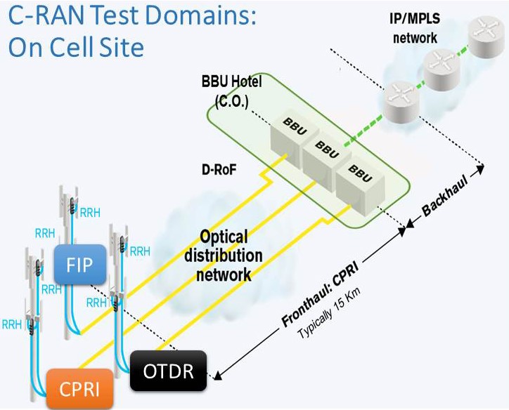
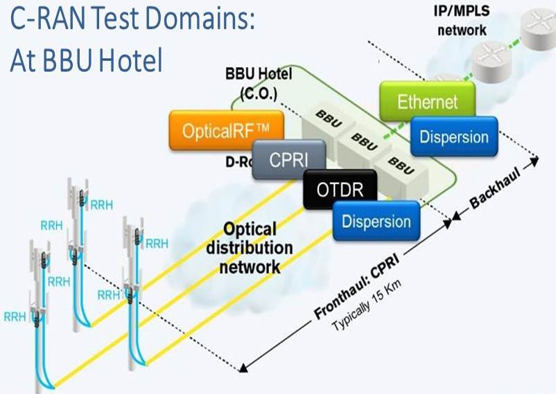
Though 5G and C-RAN is ushering in a new and more complex mobile network infrastructure, MNOs equipped with the right testing equipment can overcome any challenge in order to obtain a 5G-ready network and successfully migrate from FTTA, to C-RAN, and to Cloud RAN. As a summary, image 9 shows the critical tests to be performed at each location.
For more information about the revolutionary FTB-700G V2 Series Multiservice Tester and FTB-5700 dispersion tester, please visit EXFO at www.exfo.com. To learn more about 5G and C-RAN, please view Jean-Sébastien Tassé’s webcast From Centralized RAN to Cloud RAN.